Sunday, November 24, 2024

BetaFlight: Custom OSD Logos and Tiles

BetaFlight is flight control software used on first person view multi-rotor aircraft, it translates users inputs to motor speeds and returns information to the pilot via an on screen display (OSD) in the video feed.

The OSD information is made up of alphanumeric characters, punctuation, and other symbols arranged to convey dynamic information like battery voltage or control link quality, and static information like the pilot name. A staple of FPV flying is for pilots to add their own moniker to the OSD in order to permanently associate their name with their flying skills. Lacking any and all flying skills, I decided to spend time on customizing my moniker instead.

When you first boot your craft, BetaFlight displays a splash screen with the BetaFlight logo and information on how to access the OSD menu system.

This logo is a 288x72px tri-chrome image (black, white and green, with green being rendered as transparent) that can be replaced using a built in function of the BetaFlight Configurator software. When creating your logo image make sure the final exported image is an 8-bit RGB PNG file, if there is an alpha channel in your image it will not work.

Green is not rendered in the video feed.

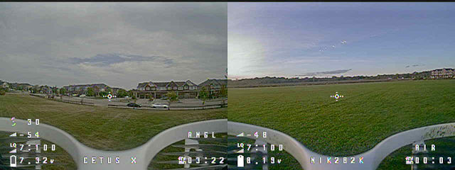
The next easiest change to make is replacing the craft's name (Cetus X) with my own, this is also easily done using the Configurator software.

That seems a little flat, the display is capable of rendering bitmaps as shown by the boot logo, battery indicator and other onscreen glyphs. It should be possible to add custom graphics to the inflight display.

The BetaFlight Cinfigurator allows for the uploading of custom fonts, with each font file consisting of 160 tiles used for OSD elements plus 96 tiles that store the bootlogo we edited earlier. After exploring the OSD menus I found that there were about a dozen tiles that were both not used in the OSD and still human typeable, this is important because there needs to be a way to make BetaFlight show the custom tiles.

A map of the tiles that are 'available' for replacement

The last 3 tiles are the crosshairs which can be placed at any location on the display, this makes them useful for adding an extra row to a single row graphic.

To get a custom image into the font it must first be fit into a number of 12x18px tiles I chose to make the 2 and 0 of my image fall exactly into one tile each, this allows them to be duplicated without filling up extra tiles. Eventually these tiles will be assigned to the characters " # @ ' , ; [ ] so when the craft name is changed to "#@',';;;[] the full logo will appear.

The tricky part is now getting these tiles into a font file. The original font files (.mcm) can be obtained directly from the BetaFlight Configurator's github they can then extracted using the MAX7456-Font-Tools (max.py) resulting in 256 numbered .PNG files. Each of the custom image tiles can now be exported to a 12x18px image of the correct number to replace the original character in the tile set, making sure that they are 8-bit RBG PNG files. Once all the tiles have been replaced the MAX-7456 font tools can be used again to re-pack the numbered .PNGs into a .mcm font file compatible with BetaFlight.

In the BetaFlight Configurator the new font file can be uploaded to the craft (as well as the custom boot logo from earlier). The craft name can then be set to the string of characters that correspond to the custom tiles and it's done.

A custom bitmap displayed inflight without disrupting any of the other functions or information on the OSD or OSD menu!

Bonus: The little Cetus X icon on the right is made of 6 tiles, the upper 3 are the crosshairs' tiles, the lower 3 are displayed using the pilot's name to get an image that is taller that one tile.

Monday, May 18, 2020

MachineMonitor.py

A few months ago I repurposed my 2010 gaming PC into a Zoneminder server to monitor some network cameras and make timelapse video. The PC has more than enough power to do the job but it has a problem with uptime, occasionally it will lock up so completely that it doesn't even respond to a ping. Troubleshooting a problem that happens less than once a month is hard but I still would like to know when it has happens so I can reboot manually. I looked at what I had available and decided on my RaspberryPi ZeroW (currently hosting a webserver), and the cheapest thermal printer on the internet.


The printer is driven by a python scrip that takes a couple arguments and sends the correct bytes to the printer to get formatted text. It had only a partial implementation of the ESC/P protocol so it is no good for images, making it a perfect choice for printing human friendly notifications. Over a couple of days I was able to map the functions that were available and come up with a workable script, as well as some really long glitch-art.


To monitor the Zoneminder and other PCs, I used another python script, it reads a list of machines from a file, pings them and then generates a notification based on whether the machine has changed state since the last time it was checked. To begin, the user (me) fills out a config file that contains a list of the IPs/Domains to be checked, and their human readable name. At regular intervals the monitoring script is run by cron, the script then pings each machine and appends "up" or "down" to each line in the config file accordingly. The next time it runs, the script compares the new up/down status to the old one and generates an appropriate message, if there has been no change in state nothing will be printed, eliminating spam. Messages are passed to the printer script along with the required formatting arguments and a messages like the following appears.


I have published the code but keep in mind I am not, by any means, a programmer. I start every project with about 15 tabs of docs.python and w3schools, I know that I am 'done' when I close the last tab. https://github.com/nik282000/Network-Machine-Monitor

Saturday, June 15, 2019

Cellular Automata!

If you've never heard of Cellular Automata here is the tl;dr.

Make a line of "cells," each cell can be on or off. Look at each cell and its neighbours, according to a set of rules you update the state of the cell in the middle. Do this for every cell in the line and then print the states of the cells on the screen as light and dark pixels. If you put each new line below the last it might look something like this.


If the 3 cells in a row form the pattern 100, 011, 010 or 001 then the middle cell will be 1 on the next generation.
All other combinations result in a 0.


Despite the simple rules, some very complex patterns or even randomness can come from the 255 rules of 1 dimensional cellular automata (the images are 2D because we are showing time starting at the top and moving downward). I've been playing with discrete automata, where the cells are either on or off, for a long time but only recently started looking at continuous automata.

In continuous automata each cell can be any value from 0 to 1 and on each step you perform a continuous function, like y = mx + b. Being continuous there is a MUCH bigger space to map, you could do any function and make infinitesimally small changes to it while still observing different results. To start I have been looking at simple rules, these look at 5 cells in a row, average them together with different 'weights' and then add a constant. If the result is greater than one then the only the fractional part is kept (the one is dropped).

For example, here are two images of continuous automata with very simple rules, they both take the average of a cell and its two nearest neighbours then add a constant value, in the first image that value is 0.04 in the second it is 0.041.


Each new cell is equal to the average of itself and its neighbours, plus an additional constant. 
New cell(n) = constant + (cell(n-1) + cell(n) + cell(n+1))/3


It becomes easy to see how many possibilities there are to generate unique patterns when adding 1/1000 to each cell makes such a big difference. To better map the possibilities I made a tool that lets me change the starting conditions (a single point or a random line of values), the weights used to average the cells together and the constant that is added to each cell on each step. Using this tool I have scanned through a few thousand rules and picked out the most interesting below, I highly recommend zooming in to see some of the fine details in the larger structures.


Friday, September 21, 2018

Text on a Graphics Display

Whenever possible I like to write my own code instead of using a library (at first). It's a challenging puzzle and often times I learn how to do something useful as well. Most recently I got a 128x64px LCD to use with an Arduino micro-controller, the display could show graphics but its built in text mode was very limited, so after getting the graphics mode running I set about building a way to turn strings into text on my display.

My basic plan was to store a bitmap of each letter and its width in an array so that I could look it up and read it back as x/y pixel locations. In order to keep my program as small as possible I had to choose the type of data I used to store the letters so that there would be very little wasted space while also being easy to maintain and update, eventually I settled on storing each letter as a 32bit integer.

The letters would have a maximum size of 5x5px, this would use 25bits, leaving 7bits for storing extra data about the letter. Initially, I used the first 4bits to store the letter's width, the next 25bits would hold the letter data and finally there would be 3 zeros at the end. The letter "A" for example would look like this:

01010111010001111111000110001000

Or for better readability:

0101    <-Character is 5 bits wide
01110   <+Bitmap of character
10001    |
11111    |
10001    |
10001   <+
000     <-Leftover bits

Unfortunately for me, C/C++ doesn't allow integers to be expressed in binary format if they are longer than 8 bits so I had to write a small program using Processing.org to scrape all the strings of ones ans zeros from a text file and then convert them into integers so my final value for storing the letter "A" ended up being 464332680.

To read back each letter and get it on screen I first extract the letter width by bit-shifting the variable 28 times, this leaves only the 4 most significant bits, and in the case of "A" this is a value of 5 "0101." Next I read back the 25 bitmap bits by shifting the variable from 27 to 4 times and masking all but the least significant bit (with the & 1):

int letterWidth = bitMap >> 28;   <-Extract the width of the letter
int i = 27;                      <-Starting at bit 27
for(int cy = 0; cy < 5; cy++){   <-Starting on row 0 and increasing to row 4
  for(int cx = 0; cx < 5; cx++){   <-Starting on column 0 and increasing to column 4
    if(((bitMap >> i) & 1) == 1){   <-If bit "i" is equal to 1 then draw a point at x, y
      point(x, y,);
    }
    i--;    <-Decrease "i" because we are moving from bit 27 back to bit 4
  }
}

Afterwards I pass the letter's width back to the string handling function so that I leave the appropriate amount of space between the letter I just printed and the one that comes next. Once this was working I used one of the three trailing zeros to indicate if the letter was a lowercase that needed to descend below the normally lowest pixel. The results are satisfactory given the small size of the display.


Sunday, August 5, 2018

Storing Data in Non-Standard Ways

While working on another BasicStamp project I found that I needed to store a lot of short sequences of instructions, specifically the addresses of the custom characters needed to to draw big fonts on an alphanumeric display.


Each big font letter is 2 blocks tall and between 2 and 4 blocks wide, each of those blocks can be filled with 1 of 7 custom characters, a blank space or a completely filled block. Its possible to just write a subroutine for each letter, but that would mean a lot of copying and pasting of code and I would have to find a way to convert the string I want to write into a series of subroutine calls.

In the interest of keeping my code short and making things modular I settled on using 2 subroutines to write strings of big font letters to the screen, the first one takes a string of 1-5 characters and looks up their character writing instructions and handles spacing on the screen. The second subroutine takes the character writing instructions and uses them to actually write custom characters to the LCD in the correct place.

The character writing instructions are 5 to 9 digit (base 10) integers, the first 4-8 digits are the custom character codes (0 = top left corner, 1 = top right corner ... 6 = lower bar, etc) in rights to left, top to bottom order, followed by a single digit that indicates the width of the big font letter (e.g. 0124563 where 3 is the big letter's width). To make them easy to look up, each code is stored in an array with an index equal to the value of each letter's ascii code ("A" = 65, "B" = 66...), that way I can take letters from a string, convert them to their ASCII code and use that value to look up the big font instruction.

So now that I had a way to turn a string of characters into a series of instruction codes I needed to be able to dissect the codes, one digit at a time. Had I used HEX values instead of base 10, I could just bitmask 0F to read out the least significant digit and then bitshift to the right by 4 bits to get rid of the current digit and move the rest down one place.

charCode = 1112223
width = charCode AND &H0F = 3
charCode = charCode >> 4 = 111222

But, had I used HEX values the 4 character wide letters' instructions that were larger than could be stored in an integer on the BasicStamp. So I went with base 10 numbers and ended up finding a more universal solution to the problem of taking apart an integer written in any base. To get the value of the least significant digit I use the modulus function, MOD 10 in this case, then I get the quotient (division without the remainder or decimal) of the integer and 10 to shift all the digits to the right while dropping the current "ones" digit.

charCode = 1112223
width = charCode MOD 10 = 3
charCode = charCode / 10 = 111222

By repeatedly using the MOD and quotient functions I could extract each digit and use them to write the correct shape to the correct location. So now my big string writing process looks like this:

Pass a 1 to 5 digit string and location to the bigString sub
bigString looks up the 5 to 9 digit charCodes in the charCode array
bigString passes the charCode and location to the bigLetter sub
bigLetter uses the charCode to write the letter to the LCD in the correct location
bigString calculates the location for the next letter
bigString passes the charCode and location to the bigLetter sub
...

By using this approach I can create new big font letters by simply adding entries to the charCode array and I have avoided having dozens of subroutines to cover each letter.

Friday, April 27, 2018

Pong with the Basic Stamp and 1602a


As my first microcontroller project I decided to make a hand-held clone of the classic game Pong. Normally a graphical display would be required for this kind of project but I decided to take advantage of the custom character capabilities of the readily available 1602a LCD. The core of the project is the updated Basic Stamp from Coridium which based on the LPC11u37 ARM microcontroller, software for the stamp is written using an updated version of basic which is very similar to the first language I had learned, Qbasic.

The wiring diagram below shows how I connected the Basic Stamp to the LCD and three inputs needed to play the game. The pushbutton with the pullup resistor R1 is used to make selections and progress through the small menu system, R2 and R3 are the potentiometers that return a 0 to 3.3v signal used to control the paddles and change selections in the menu. The 10 digital outputs are used to interface with the LCD using it’s 8-bit parallel mode, R4 is a small trimpot used to set the contrast of the display. The contrast makes a big impact on how clearly the ball’s motion is visible but only needs to be set once. Finally I used a USB battery as the power source for the project, this takes care of charging the battery and providing a stable 5v supply for the microcontroller.


With the project wired on a breadboard I could start laying out my program, the flowchart below shows how the final version of the software turned out. After being powered on there are a few tasks that only need to be done once, like sending commands to the LCD to get it started and initializing all the global variables used in the game. After the PONG splash screen is shown the user can press the button and is presented with a choice between One and Two Player Modes, to get this input I look at the current value of the analog input for the right hand potentiometer. If the analog input is greater than half of 65472, the maximum input value, then One Player Mode will be selected when the button is pressed, if the analog input is lower than half the maximum value then Two Player Mode is selected.


For a single player the game now begins but for two players there is an additional step, picking the maximum score for the round. I wanted a range from 10 to 50 using increments of 5 and came up with the following line.
maxScore = ((((65472 - AD(1)) * 9) / 65480) * 5) + 10

"65472 – AD(1)" was used to reverse the direction of the input to make clockwise motion of the potentiometer increase the score, the result will still be a number from 0 to 65472. Multiplying the 0 to 65472 value by 9 and then taking the quotient of that value and 65480 (slightly larger than the maximum) results in integers from 0 to 8. Multiplying that integer value by 5 and adding it to 10 turns the 0 to 65472 input from the potentiometer into a 10 to 50 output with evenly spaced increments of 5.

Once the game has started in either One or Two Player Mode the logic is very similar. On every cycle of the game loop the position of the paddle(s) is updated by checking the value of the analog inputs and scaling them to a value from 0 to 16 (the usable height of my display) using the same method used to pick the max score. Next the ball’s position is updated by adding COS(BallDirection) * BallSpeed to the current X coordinate and SIN(BallDirection) * BallSpeed to the current Y coordinate, by storing the ball’s coordinates, direction and speed as floating point numbers I was able to get much smoother movement of the ball than if they were all integers. Instead of cogging from one pixel to the next the ball moves smoothly and it’s position is rounded to an integer only when being displayed on screen.


After being sent to the display the game checks if the ball should bounce off of any of the walls or paddles and adjusts the direction accordingly. In One Player Mode bounces off the far wall increase the players score, if the player misses the ball with their paddle they loose a ball, in Two Player Mode getting the ball past the other player’s paddle increases the score up to the chosen maximum. If the ball is to be served on the next loop because a player missed a bounce then then a variable called gameState is set to indicate that a serve is needed and towards which player the serve will go. If the gameState variable is left untouched then the game continues as normal by updating the paddle position, ball position and then drawing it on the LCD. If the button is pushed or one of the ending conditions is met the game loop ends and the player(s) are returned to the splash screen by the main loop of the program.


The majority of the program is handled using simple math, loops and if statements but interfacing with the LCD was a big challenge for me. The LCD takes information as 8bits on 8 DB pins as well as a Register Selection pin which determines of the 8bits of data is a command or data to be written to the LCD’s memory, finally there is an enable pin which is toggled to indicate to the LCD that the current input values are valid. In order to quickly set the values of the 8 DB pins I had to learn about Bit Masking, this is where you perform a logical AND function on your data byte and a mask. For example, if I want to know the state of the x bit in this byte 0000x000 I can perform a logical AND between it and 0000100. Because all of the undesired bits in the bitmask 00001000 are zero they will always result in a zero, the value of x will however be in the result because x AND 1 = x. By using a different bit mask to check each bit of the byte I want to send I could determine which DB pins should be on and which should be off.

Where B is the byte of data I want to send then the value of each DB pin could be determined in the following way. When turning an output pin on or off in Arm Basic applying any non-zero value will turn the pin on so it doesn’t matter that the pin I use for DB7 will be told “OUT(DB 7 pin) = 10000000,” the pin will always be on when that bit is on.

DB7 = B AND %10000000
DB6 = B AND %01000000
DB5 = B AND 100000
DB4 = B AND 010000
DB3 = B AND 001000
DB2 = B AND 000100
DB1 = B AND 000010
DB0 = B AND 000001

The other big hurtle was to take the xy data of the ball and paddle positions and translate them into something that was compatible with how the LCD works. Being an alphanumeric display it is only made to show characters from it’s ROM and 8 custom characters that can be programmed by the user. These 8 custom characters are 5 pixels wide and 8 pixels tall, by arranging them in a 4 wide by 2 tall grid it is possible to create a 20x16 pixel graphical display with room for score keeping (and debugging) on either side.

Each row of a character has an address (the CGRAM address) and shows the state of the 5 lowest bits of the byte stored at that address. So my 20x16 area is split up into 64 addresses with each address containing 5 pixels each.


By mapping out the locations of the addresses I was able to make a pair of functions that would return the CGRAM address and the value of the byte that should be stored in that address for any given x and y pixel position, I could then write this byte to the appropriate CGRAM address and display the playing field.


For a more detailed explanation of the functions I used you can check out a video I did on the subject linked here: Bit Mapping on the 1602a.

Finally after about a month of development and testing I was ready to box up my portable Pong project in a suitably retro looking enclosure and call it complete.


Monday, August 28, 2017

Persistent LiveUSB Debian 9 Stretch

Live CD and USB operating systems are a great tool for working on computers with a slow or broken OS, they let you bring all your tools with you and don't need to make any changes to the host PC in order to operate. There are a number of Linux LiveCD distributions that are built for general use or specific tasks like file recover or drive partitioning but most of them lack "persistence." When you boot up a live CD/USB it is always the first boot, changes you made the last time you ran it do not carry over to the next.

Although there being a few live distributions that do have persistence, Debian, which I am most familiar with, is not one of them. After some moderate Googling I found a tutorial here: Creating a Debian Live Iso-Hybrid USB key with persistence which shows how to take the non-persistent Debian Live ISO and give it the ability to save any changes you make.

The process involves making 2 partitions on a USB stick, one to hold the operating system and one to hold any changes you make when you run the OS. The Debian Live ISO is extracted into the first partition and a few changes are made. Note in step 4 there is no longer a /syslinux/live.cfg and the word "persistence" was added to live boot option in /syslinux/menu.cfg instead. After booting the USB stick for the first time I also found it necessary to change the repository URLs in /etc/apt/sources.list to my local mirror in order to install new software.

With those two deviations from the original tutorial I was able to get a full system that can have software added and files stored and will run on nearly any PC.